FordParts
My Garage
My Account
Cart
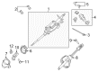
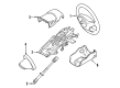
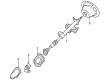
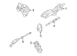
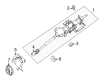
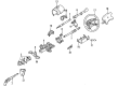
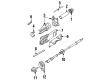
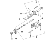
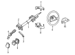
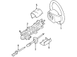
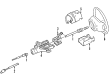
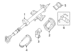
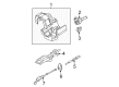
OEM Mercury Steering Column
Steering Column Tilt- Select Vehicle by Model
- Select Vehicle by VIN
Select Vehicle by Model
orMake
Model
Year
Select Vehicle by VIN
For the most accurate results, select vehicle by your VIN (Vehicle Identification Number).
20 Steering Columns found


Mercury Steering Column Part Number: CL8Z-3C529-D
$920.72 MSRP: $1068.65You Save: $147.93 (14%)Product Specifications- Other Name: Column Assembly - Steering; Column Assembly
- Replaces: 9L8Z-3C529-D, 9L8Z-3C529-C, AL8Z-3C529-A, CL8Z-3C529-A, CL8Z-3C529-C, 9L8Z-3C529-B, BL8Z-3C529-A, CL8Z-3C529-B, AL8Z-3C529-C


Mercury Steering Column Part Number: 8G1Z-3C529-A
$152.34 MSRP: $210.74You Save: $58.40 (28%)Ships in 1-2 Business DaysProduct Specifications- Other Name: Column Assembly - Steering; Column Assembly

Mercury Steering Column Part Number: 6F9Z-3C529-AA
$460.31 MSRP: $636.79You Save: $176.48 (28%)Ships in 1-2 Business DaysProduct Specifications- Other Name: Column Assembly - Steering; Column Assembly
- Replaces: 5F9Z-3C529-A

Mercury Steering Column Part Number: 5L8Z-3524-AA
$322.90 MSRP: $446.71You Save: $123.81 (28%)Ships in 1-2 Business DaysProduct Specifications- Other Name: Column Assembly - Steering; Column Assembly


Mercury Steering Column Part Number: 8L2Z-3C529-B
Product Specifications- Other Name: Column Assembly - Steering; Column Assembly
- Replaces: 8L2Z-3C529-A


Mercury Steering Column Part Number: 9E5Z-3524-A
Product Specifications- Other Name: Shaft

Mercury Upper Shaft Part Number: XF5Z3524AB
Product Specifications- Other Name: Column Assembly - Steering; Steering Column; Steering Shaft

Mercury Steering Column Part Number: F82Z3C529FA
Product Specifications- Other Name: Column Assembly - Steering; Column Assembly
Mercury Steering Column Part Number: F7RZ-3C529-MA
Product Specifications- Other Name: Column Assembly - Steering; Column Assembly
- Manufacturer Note: Tilt (fixed column is serviced by details)

Mercury Shaft Assembly Part Number: F7CZ-3524-DE
Product Specifications- Other Name: Column Assembly - Steering; Steering Shaft
- Manufacturer Note: tilt column
Mercury Shaft Assembly Part Number: F7CZ-3524-CE
Product Specifications- Other Name: Column Assembly - Steering; Steering Shaft
- Manufacturer Note: FIXED COLUMN
Mercury Steering Column Part Number: F6RZ3C529GA
Product Specifications- Other Name: Column Assembly - Steering; Column Assembly

Mercury Steering Column Part Number: 9W1Z-3C529-C
Product Specifications- Other Name: Column Assembly - Steering; Column Assembly
Mercury Steering Column Part Number: 8G1Z-3C529-B
Product Specifications- Other Name: Column Assembly - Steering; Column Assembly

Mercury Steering Column Part Number: 7L2Z-3C529-B
Product Specifications- Other Name: Column Assembly - Steering; Column Assembly
- Replaces: 7L2Z-3C529-A, 6L2Z-3C529-AA


Mercury Steering Column Part Number: 5L2Z-3C529-CA
Product Specifications- Other Name: Column Assembly - Steering

Mercury Steering Column Part Number: 7W7Z-3C529-A
Product Specifications- Other Name: Column Assembly - Steering; Column Assembly
Mercury Steering Column Part Number: 7W1Z-3C529-A
Product Specifications- Other Name: Column Assembly - Steering; Column Assembly
- Replaces: 6W1Z-3C529-A

Mercury Steering Column Part Number: 6M6Z-3C529-AA
Product Specifications- Other Name: Column Assembly - Steering; Column Assembly

Mercury Steering Column Part Number: 5L2Z-3C529-A
Product Specifications- Other Name: Column Assembly - Steering; Column Assembly
Mercury Steering Column
OEM Steering Column boasts unmatched quality. Each part goes through full quality checks. They adhere to Mercury's official factory standards. These steps remove flaws and inconsistencies. So you can get Steering Column with long life and a perfect fit. Come to our website and find genuine Mercury parts. We keep a wide inventory of OEM parts at the highly affordable prices. It's easy to search, compare, and pick what you need. You'll love the clear info and simple checkout. We offer top-rated customer service, and we reply fast. We also ship promptly to ensure your order arrives on time.
Mercury Steering Column Parts and Q&A
- Q: How to service the deployable steering column safely on Mercury Mariner?A:The first step for servicing the deployable steering column requires testing the SRS dependency then opening all SRS devices outdoors at a minimum distance of 9.14 meters (30 feet) away while using hearing protection due to deployment noise. Access to the electrical connector can be gained by either lowering down or fully removing the deployable steering column from its instrument panel position. The wiring pigtail must be removed from the original vehicle harness when deploying the column except for at least 4 inches of wire remaining available for work. Laboratory personnel must first remove the wire sheathing before exposing the cut wire ends. Two 20-gauge wires with minimum 9.14 meters (30 feet) length each should be stripped at both ends to make a jumper harness. Joint the two wires at the beginning part of the jumper harness. The deployable steering column wiring should get its corresponding wires by attaching the jumper harness ends while applying insulation to close any contact points. Structure the jumper harness at least 9.14 meters (30 feet) away from the column. A completed deployment of the steering column requires connecting the ends of the jumper harness wires to a 12-volt battery following their detachment from each other. The personnel must wait for a minimum of 10 minutes after deployment before approaching the deployed steering column. They must follow standard scrapping procedures to dispose of it correctly.
- Q: How to Service and Repair the Steering Column on Mercury Grand Marquis?A:A proper servicing and repair of the steering shaft requires initial Clock Spring removal according to safety warnings to protect yourself. Service activities first begin with disconnecting the steering column followed by detachment of the multifunction switch. The simultaneous removal of ignition lock cylinder and ignition switch should be avoided because it can hurt the ignition switch; make sure to put the ignition key in the OFF position first then take out the screw and the ignition switch while discarding the screw afterwards. Drivers must first engage the brake shift interlock solenoid manual override during column shift operations to place the gear shift lever in its lowest position before removing the three Clock Spring mounting bracket screws which should be discarded. The brake shift interlock solenoid can be removed after pulling the park position switch while releasing the attached clip together with removal of both the inhibitor spring and inhibitor. Make sure to clean these components thoroughly. The gearshift lever screw and gearshift lever must be removed before taking out the shift cable bracket with its two bolts which are also discarded. The floor shift vehicles need the removal of two bolts and the inhibitor cable bracket with bolt disposal. The floor shift procedure requires installing the inhibitor cable bracket followed by the two bolts while column shift requires starting with shift cable bracket installation and the two bolts before adding the gearshift lever and screw. Clean the grease-free space inside the inhibitor pocket where the brake shift interlock solenoid plunger rests then place the gear shift lever in the lowest gear position before fully inserting the inhibitor into its cavity while installing the inhibitor spring and applying grease both to the outer inhibitor surfaces and inside the inhibitor spring pocket. You need to insert the park position switch together with the brake shift interlock solenoid before simply connecting the clip. When installing all vehicles require the Clock Spring mounting bracket with its three screws after placing the ignition key in OFF for installing the ignition switch and its screw before moving to multifunction switch installation and proceeding to the steering column and Clock Spring.


Related Mercury Parts
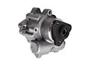 Mercury Power Steering Pump
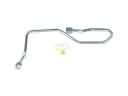 Mercury Power Steering Hose
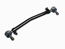 Mercury Drag Link
 Mercury Idler Arm
 Mercury Pitman Arm
 Mercury Rack & Pinion Bushing
 Mercury Rack And Pinion
 Mercury Rack and Pinion Boot
 Mercury Shift Interlock Solenoid
 Mercury Steering Column Seal
 Mercury Steering Shaft
 Mercury Tie Rod End